25.02.2025
Hydrogen electrolyser development: Improving stack efficiency by using computer simulations.
In this article, you will learn how Stargate’s Research and development teams use computer models to improve the design and enhance the stack efficiency of our electrolysers and how this approach enables engineers to explore the immense universe inside an Electrolyser Stack.
About the author

Dr. Priit Priimägi is a dedicated Computational Fluid Dynamics (CFD) engineer specializing in the simulation and optimization of alkaline electrolysers. With a PhD in electrochemical processes in electrochemical systems and fluid dynamics, he focuses on enhancing Stargate's stack efficiency and performance of hydrogen production systems.
Electrolyser stack efficiency is more than a technical goal. It is a precision challenge where every little enhancement makes a difference. Such efficiency gains can place products at the forefront of the hydrogen race where the winner is the one who spends the least amount of energy to produce the most amount of hydrogen.
In this article, you will understand how Stargate’s R&D and engineering teams use computational models to improve the design and enhance the efficiency of our electrolyser stacks and how this approach enables engineers to peek inside the complex inner workings of an operating alkaline electrolysis stack.
These simulation insights allow the team to choose the best design optimisations, guaranteeing precision and adaptability during manufacturing, placing Stargate Hydrogen’s electrolysers among the top performers on the market.
Benefits of using computer models for increasing stack efficiency
The goal of stack development activities at Stargate is to increase the efficiency and performance of our hydrogen production systems. However, the process is not easy because every design change decision that comes with a positive effect is often accompanied by a negative side-effect. Only by understanding every variable is an expert such as Dr. Priimägi able to successfully make the tricky choices and balance these tradeoffs successfully.
“By using computational models known as “digital twins”, we can study both sides of these tradeoffs, learn more about the fundamental processes occurring inside our stacks, and find the sweet spot in a virtual environment before implementing the changes in real stack prototypes,” explains Dr. Priimägi
The most common tradeoffs that need to be considered when designing an alkaline electrolysis stack:
1) Number of cells: stack productivity versus electrolyte distribution – Stack efficiency can be easily increased by adding more electrochemical cells in series, but at the same time the distribution of the KOH electrolyte between the cells can become more unbalanced, with some cells receiving more electrolyte than others.
2) Manifold size: pressure drop versus parasitic currents – In general, large manifolds with short channels result in low stack pressure drop. Low-pressure drop is beneficial, as this means you do not need powerful pumps for recirculating the KOH electrolyte, and the stack becomes less of a bottleneck for the fluid flow.
However, if the manifold is too large, some of the stack current bypasses the electrodes, and moves through the manifold instead. This phenomenon is referred to as shunt currents and these have a negative impact on stack efficiency.
3) Diaphragm thickness: resistance versus gas crossover - A thicker diaphragm results in an increased ionic resistivity of the cell, reducing cell performance, but also results in higher purity of the gases, reducing the need for purification processes.
4) KOH electrolyte flow rate: cell resistance versus electrolyte pump size – Higher electrolyte flow rates through the cell decrease the amount of gas bubbles in the cell and therefore, decrease the cell voltage. However, for that to work stronger pumps would be needed with higher running costs and an overall system efficiency drop.
5) KOH electrolyte flow rate: temperature gradient versus gas/liquid separator size – A higher electrolyte flow rate applied for the stack can decrease temperature gradients over the cell. This means that the temperature in different parts of the cell is more uniform, which results in uniform activity of the electrode over its entire surface. On the other hand, the rate at which the gas-electrolyte mixture needs to be recirculated through the system will increase, requiring bigger gas/liquid separators and hence system cost increases.
6) Porous transport layer: mechanical compression and internal stresses versus Ohmic resistance – Thicker and stronger porous transport layers require a higher stack compression force, resulting in increased internal mechanical stresses inside the stack.
On the one hand, this requires stack internal components to be stronger and hence more expensive but, on the other hand, the cell contact (also known as Ohmic) resistances are lower and the stack efficiency increases.
7) Operating pressure: Stack efficiency versus component cost – Higher operating pressure decreases the amount of bubbles in the cell, which in turn enhances the cell performance, but the cost of the components increases due to stricter requirements for mechanical strength. The latter results in longer design and testing phases for the components.
8) Operating temperature: Stack efficiency versus corrosion, stability, and cost - Higher operating temperature increases the electrochemical activity as well as the conductivity of the KOH electrolyte but on the other hand, it increases the corrosion rate of stack components. The risk of higher corrosion rates means that more expensive materials are needed to keep the degradation under control.
Computational power needed to increase stack efficiency
Full-scale stack simulations are mathematically so complex that recreating a real-world scenario in full detail is practically impossible. The sheer number of variables, calculation points, and fluid dynamics involved make the process extremely demanding in terms of the required computing power.
“Even with a supercomputer, some level of simplification will be needed. Some variables, like temperature current density, are often fixed to make the model manageable in terms of the required computing power. Alternatively, the stack model can be broken into smaller sections. Without these adjustments, the computational load would be too high to obtain simulation results in a reasonable amount of time.
Digital Twin build-up explained step-by-step
“At Stargate, in the pursue of the best stack efficiency, we split the build-up of a stack-level computational model into 5 steps. In each step, extra elements are added, and the model gets more complex, but also a more realistic representation of the real-life stack,” explains Dr. Priimägi.
Step 1 – Establish a flow model in an empty cell
In this first step towards increasing stack efficiency, the geometry of the cell is established, and a simple, laminar flow simulation is carried out, mimicking a situation where the electrolyser is operating in an idle mode with no electrolysis current applied and hence no gas production.
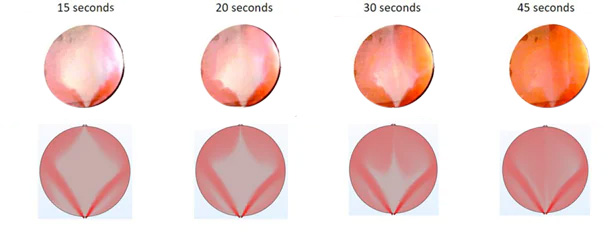
The results of the simulation are compared against experimental results where an electroyser single cell with transparent end plates is used, allowing the team to see the flow of liquid inside the cell as it happens. The evolution of fluid flow inside the cell is made visible by injecting colored ink into the electrolyte, as you can see on the sequence of images below.
The top row of images are actual photos showing the evolution of liquid flow inside the cell 15 seconds, 20 seconds, 30 seconds, and 45 seconds after red ink was injected into the electrolyte flow. It can be seen, that in a situation where the cell is empty, i.e., there is no porous transport layer to guide the fluid flow, the electrolyte distribution across the surface of the cell will be very uneven, with the flow preferentially being pushed to the sides of the cell. The same trends are visible in the corresponding simulation results: initially, there is very little ink (shown in red) in the middle of the cell, but over the course of the simulation, the distribution becomes more uniform.
The above tests were done as part of a Clean Hydrogen Partnership project called ENDURE.
The ENDURE project is a research and innovation project for which Stargate Hydrogen is the coordinator. Its main objective is to improve the current density and stability of electrolysers, bringing the stack efficiency and durability of alkaline electrolysers to a new level.
The stack-level simulation work package in the project is led by Dr. Priimägi from Stargate, while the cell-level simulation tasks are carried out in close collaboration with Prof. Joris Proost’s group from Universite Catholique de Louvain (UCLouvain). Click here to learn more about the ENDURE project.
Step 2 – Simulate the flow of liquid in a cell with a simple porous transport layer
In the second step, the model is made more realistic by including a porous transport layer in the cell. The role of this layer is to distribute the incoming electrolyte evenly across the cell, as well as to act as a means of transporting electrons from the bipolar plate to the cathode, as well as from the anode to the bipolar plate.
In the series of images below, the top row of images shows again the results of transparent cell measurements with red ink being injected into the active area of the cell from the bottom. Similarly to the results in step 1, ink distribution over the cell improves with time, but the distribution in the cell with a porous transport layer is significantly more uniform compared to the empty cell used in step 1.
Simulation results are in good agreement with experimental results: the shape of the ink plume and the time it takes for the ink to transverse through the cell match nicely between the images on the top with the images at the bottom.
Step 3 - Switching from a simple porous transport layer to advanced porous electrodes
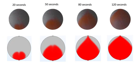
In the third step towards increasing the stack efficiency, a single-phase water flow model of a cell consisting of an advanced porous electrode (based on nickel foam) is added to the simulation and the model is once again validated against real-life experiments. The results of the corresponding experiments and simulation results are shown in the figure below.
The top row of images shows the outcome of ink injection experiments as a function of time after the ink was introduced into the cell from below. The second row of images are the results of computational fluid dynamics simulations using nickel foams as electrodes. Again, there is a clear agreement between experimental data and simulations, validating the modelling approach.
With a validated model, it is now possible to study the electrolyte flow rate inside the cell, change the cell geometry and design, or modify the properties of electrolyte inlet channels to improve flow homogeneity inside the cell and therefore the stack efficiency.
“The post-processing of the results for flow field and field homogeneity evaluations can be carried out using residence time analysis, which we have developed together with our partner in the ENDURE project, UCLouvain,” comments Dr. Priimägi. “Residence time analysis allows us to compare design modifications in a quantitative manner.”
Step 4 - Including gas phase into the model
In this step, the gas phase (bubbles) is added to the calculations. From this point onwards, the simulations become computationally much more demanding since all forces are no longer only calculated for the liquid phase (electrolyte), but also for the gas phase (hydrogen gas on the cathode side and oxygen gas on the anode side).
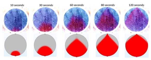
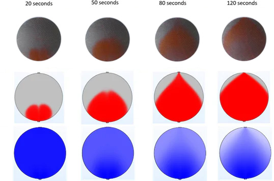
The results are summarized in the figure below. Compared to previous figures, an additional row of images is included, which describes the distribution of gas inside the cell during operation. During the initial stages of the simulation, there is no hydrogen inside the cell and the cell is uniformly blue in color.
As the electrochemical reaction proceeds across the cell area, more and more hydrogen is generated. This hydrogen starts to accumulate at the top part of the cell, indicated by the lighter blue and white colors that become more prominent in later simulation images. Gas accumulation at the top of the cell is a common phenomenon in all electrolysis cells.
If not properly accounted for, it can lead to the partial deactivation of the cell: in areas where electrodes are exposed to hydrogen and not the KOH electrolyte, no electrolysis reaction can proceed. One way of tackling this challenge is to significantly increase the rate of electrolyte flow into the cell and therefore the stack efficiency.
This is exactly what project partners in the ENDURE project are working on, building upon some very promising results recently published by UCLouvain’s team in Nature Communications. The simulation tool described was developed as part of the ENDURE project and will play an important part in optimizing the performance of cells and stack efficiency.
Step 5 – Stack level model
Being able to describe the phenomena occurring in single electrolysis cells to a high degree of accuracy is an important prerequisite for expanding the simulation approach to the stack level. After all, green hydrogen production in industrial settings is always carried out with the help of electrolysis stacks, which are made of many electrolysis cells connected electrically in series. In a stack model, gas and liquid flow along with electrochemical reactions are evaluated for each cell. Since the physics and geometry of the stack are too complex to tackle all at once, the mathematical problem is once again broken into smaller bits.
“First, we study a single half-cell, then a simplified stack model, and finally, a full electrochemical stack model,” says Dr. Priimägi. “The goal is to solve the relevant mathematical equations for all areas where gases and the electrolyte are moving — both separately and together.”
He continues: “Starting with the half-cell model, running simulations under different KOH flow conditions helps us understand how the gas and liquid phases are distributed and how much pressure is lost as they move through the system. At this stage, we fix the applied current to keep the gas production rate steady.”
The results from the half-cell models are used for evaluating the fluid flow inside the stack manifolds. Since no mass is lost or created an imbalance in one of the half-cells affects the others. If one cell gets less electrolyte, another might get more. All these aspects are taken into account until a coherent simulation result is obtained.
Finally, detailed electrochemistry is added. In this last stage, the model calculates the voltage of each cell based on the applied current, electrode reactions, and energy losses from materials and contacts. The model keeps adjusting until the balance between electrical charge sources, sinks, and resistance pathways are reached.
Putting the Model to Work
Once the model is fine-tuned and it aligns with experimental performance data, the most exciting part of the development process can begin: making predictions about how the stack with a modified design is expected to perform. Furthermore, the model will also allow Stargate engineers to estimate stack efficiency under a range of operating conditions.
“We can start adjusting parameters and component dimensions to achieve a steady KOH flow throughout each cell in the stack,” mentions Dr. Priimägi “This helps us improve stack efficiency by ensuring that fresh electrolyte moves evenly through the system without backflows or dead zones, which can trap hydrogen and lower performance.”
He concludes: “The final stack-level model also provides insight into pressure build-up and gas distribution in cells and manifolds during operation. Measuring these values directly is difficult, but simulations let us see how gas moves and behaves inside the stack. This is especially useful when selecting manifold and channel sizes to obtain the best performance.”
Conclusion
At Stargate Hydrogen, digital models such as the ones highlighted above are used extensively to enable the development of high-performance electrolysis stacks and systems. By streamlining the development process, reducing costs, and enhancing performance, these digital twins ensure that the journey from concept to implementation is efficient and effective.
Stargate Hydrogen continues to be dedicated to pushing boundaries to enable the industry of tomorrow. In contrast to many of our competitors, Stargate technology is not based on decades-old legacy designs but relies on recent advances in material science and engineering. If you want to dive deeper into our work, please visit our website.
Let’s accelerate the transition to a sustainable future — together.